
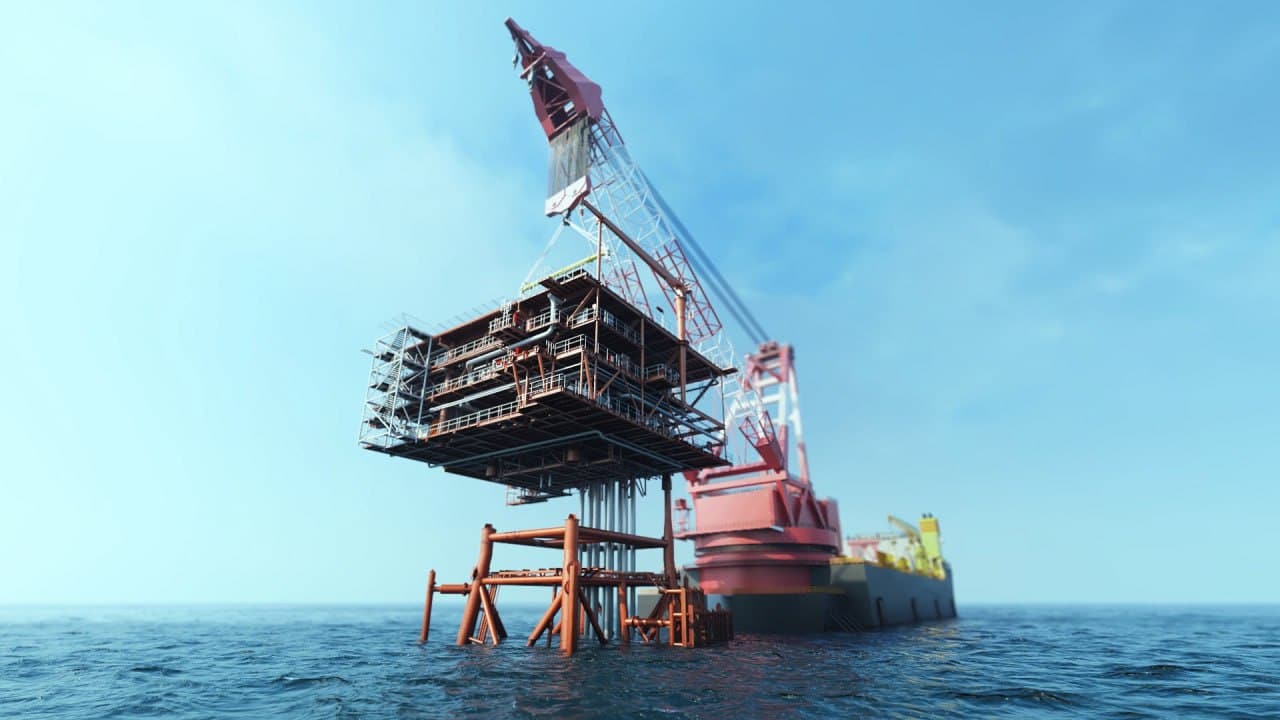
Building an offshore platform may look, to an outside observer, like little more than an enormous steel construction project. In reality, a significant part of the project’s complexity begins only after the structure leaves the fabrication yard and must be transported to a remote location at sea and installed in its final position. A successful offshore platform installation is the result of precise coordination between structural engineering, marine operations, heavy transport, lift engineering, lifting equipment, weather conditions, and operational planning.
In many oil and gas and offshore facilities projects, structures such as jackets and topsides are fabricated in one or more sections at a fabrication yard and then transported offshore for installation. In the heavy-lift crane method, the structure is lifted from a barge by a heavy-lift crane vessel and placed in its designed position. The same general principle applies to topsides, although the detailed procedure depends on the weight, dimensions, centre of gravity, structural design and the capacity of the installation vessel. So how exactly is this process carried out?
From Fabrication Yard to Sea – The First Stage: Loadout
Once construction of the structure is complete, the first major challenge is transferring it from the fabrication site onto the transport vessel. In the offshore industry this operation is known as loadout. Depending on the weight and dimensions of the structure, the facilities available at the fabrication yard and the design of the quay, different loadout methods may be used. One common method is the skidding system: the structure is placed on skid beams or dedicated tracks and moved toward the barge using hydraulic systems, strand jacks, winches or push-pull equipment. Another method is crane loadout, in which the structure is transferred onto the barge by shore-based cranes or other lifting equipment.
In large projects, the loadout operation itself is treated as an independent engineering project. The structure’s weight, centre of gravity, quay load-bearing capacity, barge condition, water depth, tidal conditions and the method of transferring load from the structure onto the transport system must all be carefully analysed in advance. In many cases, controlled ballasting and deballasting of the barge is carried out simultaneously to maintain the barge’s trim and stability during the load transfer. In some projects the structure is first moved within the yard using SPMT (Self-Propelled Modular Transporters) and is then transferred onto the barge by skidding systems or other suitable equipment.
The objective appears straightforward:
Fabrication Yard → Quayside → Loadout → Transportation Barge
Yet behind this short path lies a substantial volume of engineering calculations and operational planning.
Seafastening – Preparing the Structure for the Sea Voyage
lacing the structure on the barge does not mean it is ready to sail. After loadout, the structure must be securely connected to the barge. This stage is known as seafastening. During the voyage the barge and structure are subjected to various motions caused by waves and sea conditions. The structure must therefore be restrained in such a way that these motions do not cause displacement, structural damage or unacceptable loads at the connection points.
At this stage engineers examine:
- Structure weight and weight of associated equipment
- Centre of gravity
- Loads induced by barge motions
- Wave-induced loads
- Longitudinal and transverse accelerations
- Barge stability
- Connection points between structure and barge
- Location of supports and grillage
- Metocean conditions along the transport route
The design of the grillage and seafastening must be capable of resisting the dynamic forces while also allowing rapid and safe release during the subsequent lifting operation. In essence, a structure that has been designed for offshore operating conditions must first be able to complete a safe sea voyage. Once seafastening is complete, the necessary inspections are carried out and the barge is prepared for sail-away. In real projects even the departure from the quay requires careful planning, as the barge must transition from the quayside condition into a state suitable for towing or transit.
Marine Transportation – The Journey to the Offshore Field
The structure is now on the barge and ready to sail.
Depending on project size, distance from the fabrication yard to the offshore field, structure weight and sea conditions, a heavy transport vessel, material barge or cargo barge may be used.
During the voyage the issue is not simply “carrying a heavy structure on water.” The dynamic behaviour of the combined barge-plus-cargo system must have been analysed under a range of sea states.
Waves, wind and current can induce:
Roll – Pitch – Heave – Yaw – Surge – Sway
These motions can generate significant forces in the structure and the seafastening system. For this reason, marine transportation analysis, stability assessment and structural response evaluation form an essential part of offshore transport planning. Metocean studies also play a key role in ensuring that the actual wave, wind and current conditions along the route are properly modelled. At the same time the marine route must be examined for water depth, traffic restrictions, weather conditions, possible support ports and the optimal sailing window.
In major offshore projects the selection of a suitable weather window can have a direct impact on the installation schedule and operational cost.
Arrival at the Installation Site – Where the Real Operation Begins
Once the barge reaches the field area, the transport operation enters a more critical phase. The barge must now be positioned correctly relative to the installation location, and the heavy-lift crane vessel must prepare for the lifting operation. The crane vessel must be positioned with very high accuracy relative to the installation site. Depending on the vessel type, positioning may be achieved using anchor lines, thrusters, Dynamic Positioning (DP) systems, or a combination of positioning and mooring equipment.
At this stage the following factors become critical:
- Water depth
- Current
- Wind
- Wave height
- Vessel motion
- Crane capacity
- Crane radius
- Lift height
- Load weight
- Centre of gravity
- Rigging configuration
An important point is that the nominal crane capacity alone does not determine whether the operation is feasible. Crane capacity can be significantly reduced as the working radius increases and as operational conditions change. Engineers must therefore verify that the crane can lift the structure from its position on the barge and maintain full control throughout the entire path to the final installation point.پ
Rigging – Connecting the Structure to the Crane
Before the lift begins, the rigging system is connected to the structure. The structure is designed from the outset with dedicated lifting points, commonly known as padeyes or lifting points. Slings, shackles, spreader beams and other rigging equipment are selected on the basis of the structure’s weight, geometry and centre of gravity. In many projects active heave compensation systems are also employed to reduce the effect of the vessel’s vertical motions on the load.
The objective at this stage is not merely to “lift” the structure; it is to ensure that the forces generated during the lift remain within acceptable limits for both the structure and the equipment. Even a small change in sling angle or connection point can alter the force distribution. For this reason, lifting analysis is one of the key elements of offshore installation engineering.
Offshore Lift – The Moment the Structure Transfers from Barge to Crane
After the rigging is complete and final checks have been carried out, the lifting operation begins. The crane load is increased gradually until the full weight of the structure is transferred from the barge to the crane. Once the load has been fully transferred, the seafastening that connects the structure to the barge is released or disconnected according to procedure, and the crane lifts the structure clear of the barge. At this moment the structure is, for the first time, controlled solely by the lifting system.
Movement of the structure must be controlled with extreme precision because, unlike a conventional onshore lift, both the crane and the barge are subject to the motion of the sea. Consequently, offshore lifting operations are normally performed only within a defined weather window. Continuous monitoring of environmental conditions and real-time communication between the various teams are integral parts of this stage.
Moving the Structure to Its Final Position
Once the structure is completely clear of the barge, the crane vessel moves it toward its final position. This movement may involve changes in elevation, changes in radius, slewing of the crane and simultaneous control of the vessel’s motion. In heavy-lift operations, coordination between the crane operator, the marine operations team, the rigging team, the survey team and the vessel command is of the highest importance. Precise survey and positioning systems (including DGPS and underwater acoustic systems) are essential to ensure the structure is placed correctly.
Ultimately the structure must be positioned with very high accuracy relative to the jacket, foundation or other substructure elements. In many cases stabbing guides and temporary guidance systems are used to assist alignment, and the lowering operation is performed under controlled speed (soft landing) to avoid sudden impact.
In jacket installation the final objective is to place the structure in its designed position on the seabed. After placement, pile installation and structure stabilisation are carried out. In certain configurations the jacket is connected to the seabed by piles installed through pile sleeves. At this stage ROVs are frequently used for underwater monitoring and final verification of the installation.
Topside Installation – Placing the Operational Heart of the Platform on the Jacket
Once the jacket has been installed and stabilised, it is the turn of the topside installation. The topside is the part of the offshore platform that houses the main process equipment, piping, electrical systems, accommodation, control systems and other facilities required for operation. In the crane-lift installation method the topside, or its modules, are lifted by a heavy-lift crane vessel and set down on the jacket. At this stage alignment is of critical importance.
The topside must be placed exactly on the designed points, after which the structural connections between topside and jacket are completed.
The project then moves into the hook-up phase, in which systems such as piping, electrical, instrumentation, utilities, risers and other interfaces are connected to one another.
After hook-up is complete, commissioning and system testing are performed so that the facilities are ready to enter the operational phase. Final inspections, including NDT of critical connections and HSE reviews, are also carried out before production operations begin.
Why Offshore Installation Is More Than Just a Lifting Operation
Sometimes images of a crane vessel lifting an enormous structure appear to summarise the entire offshore installation process in a single frame.
The reality is far more complex. A successful offshore installation is the result of the integration of multiple disciplines:
- Structural Engineering
- Marine Engineering
- Heavy Lifting
- Rigging Engineering
- Naval Architecture
- Offshore Construction
- Transportation Engineering
- Survey & Positioning
- Weather Planning
- Subsea Operations
Each of these areas must be coordinated with the others.
For this reason, before the actual operation is executed, many offshore companies use installation analysis, simulation, engineering visualisation and technical animation to examine and communicate the operational sequence.
A specialised animation can transform what is scattered across dozens of pages of engineering documents, drawings and procedures into a clear visual sequence that can be understood in a few minutes.
Why Technical Animation Matters for Offshore Installation
In complex offshore projects, not all stakeholders share the same technical language. A lifting engineer may be completely familiar with rigging configuration and crane radius, while an investor, project manager or end client may be unable to visualise how the operation will actually be performed from the same drawings. This is where 3D technical animation becomes a powerful engineering and communication tool. Using an accurate three-dimensional model it is possible to show, step by step:
- Loadout
- Barge transportation
- Seafastening
- Heavy lift
- Crane vessel positioning
- Rigging
- Jacket installation
- Pile installation
- Topside installation
- Offshore hook-up
- Subsea connections
- Cable installation
This type of visualisation is not merely for marketing purposes. It can be used in engineering communication, client presentations, HSE training, project approval processes, tender documentation, investor presentations and operational planning.
International Energy Club – Turning Complex Offshore Operations into Clear Visuals
At International Energy Club (IEC) we have focused for years on exactly this point: converting complex energy, marine and offshore technologies and operations into technical images and animations that are understandable to both specialists and non-specialists. As a global reference in Offshore, Marine, Subsea & Renewable Energy Animation, IEC has produced specialised projects for numerous companies around the world and has extensive experience in the visualisation of offshore operations.
One of the areas in which we have repeatedly produced specialised animations is Offshore Platform Installation – from the transport and loadout of structures through to the lifting operation and the final placement of the various components. In addition, IEC has produced a highly specialised animation on another topside installation method – Float-Over Installation – a method whose details we have not covered in this article, but which further demonstrates IEC’s ability to transform complex offshore operations into precise and comprehensible visual experiences.
For us, creating an offshore animation is not simply about building a beautiful three-dimensional model. First we must understand the technology, the equipment, the engineering sequence and the operational logic, and only then translate them into the language of imagery. Because in the energy industry, a good image is valuable only when it can convey a complex engineering concept accurately, clearly and reliably.
Final Thought
The installation of an offshore platform, from the moment the structure is ready at the fabrication yard until it stands in its final position at sea, is a chain of interconnected and sensitive operations:
Loadout → Seafastening → Marine Transportation → Offshore Positioning → Rigging → Heavy Lift → Installation → Piling → Topside Installation → Hook-up
Each stage requires calculations, equipment, specialised personnel and precise planning. And perhaps the best way to understand this complex chain is to see it. This is precisely where 3D Engineering Visualisation can close the gap between engineering documents and a real understanding of the operation.
Read More: Oil & Gas Animations